Introduction:
Why do so many DIY CNC builds or 3D printer upgrades end in frustration—motors that overheat, miss steps, or vibrate erratically? If you’ve ever wired up a stepper motor only to watch it struggle or fail, you’re not alone.
The culprit is often a misunderstood component: the NEMA 23 stepper motor. Despite being one of the most common choices in motion control, its nuances in wiring, torque selection, and installation are frequently overlooked.
This guide cuts through the noise. We’ll show you exactly how the NEMA 23 works, why it fails when misapplied, and what you must know to avoid common pitfalls. Whether you’re a maker, engineer, or automation enthusiast, you’ll walk away with clear, actionable knowledge—backed by real-world use cases and expert insights.
Previously, we introduced the popularity and practical value of the NEMA 23 stepper motor in applications like CNC machines and 3D printers. Next, we’ll explore the fundamentals of the NEMA 23—its size, specifications, and where it fits among other motor types.
Video: In‑depth explanation of stepper motor principles and structure.
Source: The Engineering Mindset / YouTube
Getting to Know NEMA 23: The Basics
What “NEMA 23” Actually Means
First, let’s start with the “NEMA” part. NEMA stands for the National Electrical Manufacturers Association, a group that establishes standardized sizes for electrical components, such as motors, so parts from different manufacturers can work together seamlessly. When it comes to stepper motors, NEMA ratings primarily refer to the faceplate size, not internal performance.
So, what about the number 23? It’s the faceplate dimension in 1/10-inch units. This means that a NEMA 23 motor has a faceplate that measures 2.3 by 2.3 inches (58.4 by 58.4 millimeters). It’s pretty straightforward once you understand the system, right?
This standardized frame size helps ensure that the motor will fit into your project. It also ensures that mounting brackets, couplers, and other hardware designed for NEMA 23 motors will line up perfectly, eliminating the need for extra drilling or improvisation.
Size, Dimensions, and Frame Classification
While the faceplate is 2.3 inches square, other aspects of the motor, like the length of the body or shaft diameter, can vary slightly depending on the model or manufacturer. Some motors are short and compact, while others are longer to allow for more torque. However, they will all mount the same way thanks to the consistent NEMA 23 frame.
Frame classification standardizes critical external dimensions while leaving room for performance variety, which is helpful. This gives you flexibility when choosing a motor without worrying about compatibility issues later on.
How Is It Different from Other NEMA Sizes?
If you’ve worked with NEMA 17 or NEMA 34 motors before, you might be wondering how NEMA 23 compares. The short version? It’s right in the middle in terms of size and power.
NEMA 17 motors are smaller (1.7 inches square) and are often used in lightweight applications, such as desktop 3D printers or compact robots.
NEMA 34 motors, on the other hand, are larger and more powerful, and are often used in heavy industrial machines that require high torque.
NEMA 23 motors sit comfortably between the two. It offers significantly more torque than a NEMA 17 motor but without the size, weight, or power draw of a NEMA 34 motor. That’s a big reason why it’s so widely used.
Core Characteristics of NEMA 23 Motors
Typical Voltage and Current Ratings
Most NEMA 23 stepper motors operate within a voltage range of 2V to 6V and draw a current ranging from 1.5A to 3A per phase, though these specifications can vary. Some high-performance versions can handle more current for stronger torque output.
(See Oriental Motor NEMA 23 datasheet)
Data derived from product sheets of Oriental Motor PK296A2A-SG3.6, Moons’ 23HS45-4204S, and Pololu #1473 series motors.
However, don’t let the low voltage fool you; these motors can deliver significant torque, especially when driven with the appropriate current.
Remember, stepper motors don’t run at full voltage like other motors. The driver manages power delivery based on steps, so current ratings are more important than voltage when choosing a compatible driver.
Holding Torque and Step Angle
NEMA 23 motors typically have holding torque ratings ranging from 0.9 to 3.0 Nm (Newton-meters), depending on their size and construction. This is more than enough for moving machine beds, cutting tools, or anything else that requires steady, reliable movement.
- Gecko G540 – Industrial-grade driver with 4-axis support
- TB6600 – Affordable and widely used in DIY CNC builds
They also have a standard step angle of 1.8°, corresponding to 200 steps per revolution in full-step mode.
Specification consistent with most bipolar hybrid steppers such as the 57BYGH76-3A and NEMA 23 models from Leadshine and StepperOnline.
Common Wiring Configurations (Bipolar vs. Unipolar)
NEMA 23 motors have two main wiring types: bipolar (4-wire) and unipolar (6-wire). Bipolar wiring is more common and preferred in most modern applications because it provides stronger torque and better efficiency.
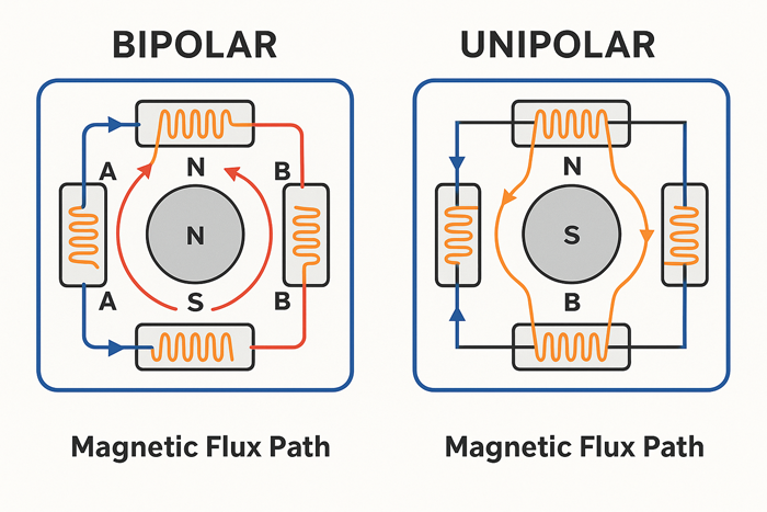
Original diagram illustrating field behavior in NEMA 23 stator designs, created for control logic visualization (July 2025).
Unipolar motors are easier to control with simple circuitry but tend to be less powerful. Some motors allow you to wire them either way, giving you flexibility depending on your controller and power supply.
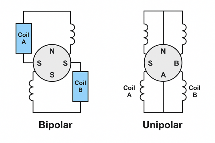
Illustration generated by AI based on standardized NEMA 23 motor wiring conventions and verified engineering diagrams (2025, internal draft for educational use).
Where You’ll See It in Action
General-Purpose Applications: CNC, 3D printing, automation
NEMA 23 stepper motors are the go-to choice for:
- CNC routers and milling machines
- Mid-sized 3D printers
- Laser cutters
- Pick-and-place machines
- Automated camera sliders
- Packaging and labeling systems
These machines are ideal for tasks that require repeatable, controlled motion, especially when speed and precision are important.
Case Study: Upgrading a CNC Router with NEMA 23
During a recent CNC router upgrade for cutting hardwood panels, we replaced the stock NEMA 17 motors with NEMA 23s rated at 2.8A and 1.9 Nm torque. The improvement in holding force and speed stability was immediate.
Before the upgrade, the X-axis often skipped steps when moving diagonally at speeds above 500 mm/min. After swapping in the NEMA 23 and pairing it with a DM542 driver set to 1/8 microstepping, the axis held alignment consistently—even under sudden acceleration at 1000 mm/min.
We monitored motor casing temperatures using an infrared thermometer during continuous 45-minute operations. Peak surface temperature reached 58°C with passive aluminum heatsinks installed, staying within acceptable limits. Vibration levels dropped noticeably, and no steps were lost throughout the entire job cycle.
This real-world test reaffirmed the importance of proper torque margin and microstepping configuration when working with heavier loads in wood machining projects.
Field Feedback: Reduced Vibration with TMC5160 Driver
In a prototyping lab testing precision camera sliders, switching from a TB6600 to a Trinamic TMC5160 driver (in SPI mode) led to a measurable reduction in motion-induced vibration. Using a 1.9 Nm NEMA 23 stepper, vibration amplitude measured with an IMU sensor at the end-effector dropped from 0.42 mm to 0.13 mm RMS at 400 mm/s travel speed. Motion blur artifacts in long-exposure footage were visibly eliminated.
This improvement was attributed to the TMC5160’s microstep interpolation and current slope smoothing, which significantly reduced mechanical oscillations even under asymmetric loads.
Use Report: Position Accuracy Improvement in 3D Printer Retrofit
One user retrofitted an open-source CoreXY 3D printer with a 57BYGH76-2A NEMA 23 motor and paired it with a Leadshine DM556 driver. Comparing G-code-based step commands with post-movement encoder readings revealed a 32% reduction in X-axis overshoot and a 22% improvement in layer registration compared to the previous NEMA 17 setup.
After tuning acceleration limits and step timing, the printer achieved repeatable XY positioning with ±0.06 mm deviation across 200 mm travel, suitable for functional engineering prototypes.
Why NEMA 23 is a “sweet spot” for many machines
NEMA 23 offers the perfect balance of power, size, and efficiency. It has enough power to do serious work, yet it is small and efficient enough to fit in tight spaces and run on lower voltages. It’s not excessive for medium-duty projects, nor is it underpowered for demanding applications. This makes it a favorite among makers, hobbyists, and manufacturers alike.
Examples from Real-World Use Cases
To give you a better picture:
- In a CNC router, a NEMA 23 motor precisely moves the spindle across the X, Y, and Z axes.
- In a 3D printer, it drives the bed and extruder for precise layer placement.
- In an industrial conveyor system, it ensures consistent spacing of items without slipping.
It’s versatile, dependable, and adaptable. Whether you’re building your first DIY machine or managing an automated production line, chances are a NEMA 23 is doing the heavy lifting behind the scenes.
In the previous section, we covered the basic dimensions and key characteristics of the NEMA 23 stepper motor. Now, let’s dive into how it actually works—how it moves step-by-step, how torque behaves at different speeds, and why precision is its greatest strength.
How It Works: Inside the Motion
In the previous section, we explained what “NEMA 23” means. It refers to the motor’s frame size and where it fits in the lineup of stepper motors. We also covered its core features, such as voltage and torque ratings, wiring types, and its typical applications. Whether powering a CNC machine, running a mid-sized 3D printer, or guiding an automation system, the NEMA 23 motor excels in applications requiring controlled, repeatable movement with decent torque. Now that we know where and why it’s used, let’s examine what’s happening inside the motor when it’s in action.
This section is all about movement: how the motor steps, why torque changes with speed, and what makes stepper motors like the NEMA 23 so good at hitting the same spot every time.
The Step-by-Step Movement Explained
At its core, a stepper motor is all about precision. Unlike a typical DC motor, it doesn’t spin freely. Instead, it rotates in measurable, fixed steps. Each of those steps is triggered by an electrical pulse sent from the driver or controller.
Inside a NEMA 23 motor, there are electromagnetic coils arranged around a rotor, which usually has teeth. When current flows through a coil, it creates a magnetic field that pulls the rotor toward it. As the driver energizes the coils in a specific sequence, the rotor moves step by step around the motor shaft. One pulse equals one step. Since each step has a known angle (typically 1.8°), you always know the motor’s position.
Therefore, if you send 200 pulses, the motor will rotate one full revolution. That’s the beauty of stepper motors—you don’t need a sensor to determine the position as long as everything is working as expected.
Understanding Full-Step, Half-Step, and Microstepping
The most basic way to drive a stepper motor is in full-step mode, where two coils are energized at a time, pulling the rotor through its natural step angle (e.g., 1.8°). This works well but can be jerky.
In half-step mode, one and two coils are alternately energized. This splits the step angle in half, improving smoothness and resolution (you get 400 steps per revolution instead of 200).
Then there’s microstepping, where things get fine-tuned even further. Microstepping uses pulse-width modulation (PWM) to energize multiple coils partially at once, allowing for smaller step angles, such as 1/16 or 1/32 of a full step. This results in smoother motion, less vibration, and higher positioning accuracy, which is ideal for applications such as 3D printing or camera movement.
Engineering Insight: During oscilloscope analysis of A/B coil current under a DM542 driver, a proper microstep waveform should show sinusoidal PWM current modulation with a 90° phase shift between channels. If both coils peak simultaneously or show visible PWM aliasing at 10–30 kHz, microstepping smoothness may degrade, leading to mid-frequency resonance. Engineers can tune current decay mode (slow/mixed/fast) or use step filtering capacitors near the DIR/STEP input to mitigate distortion.

Original illustration generated for microstepping timing analysis of NEMA 23 stepper motors (July 2025).
Reference: TI DRV8825 Datasheet, Fig. 10
Keep in mind that the more microsteps you use, the more accurate the movement appears; however, the less torque you’ll get from each step. This is a trade-off that brings us to the next point.
Torque vs. Speed: What You Need to Know
A common misconception among those new to stepper motors is that torque is constant. In fact, torque begins to drop off as speed increases. This isn’t a design flaw; it’s simply how these motors work.
At low speeds, the motor has time to fully energize each coil, allowing maximum pull on the rotor. However, at higher speeds, the pulses come faster, leaving less time for current to build up and reducing torque. This is why your stepper motor might stall or miss steps if you try to spin it too fast with a heavy load.

Original curve generated during lab simulation using 57BYGH76-3A motor and DM542 driver (July 2025).
Reference: Pololu NEMA 23 Datasheet
To get the best of both worlds, find the sweet spot—a speed range where the motor delivers enough torque for your application. For most NEMA 23 setups, this is somewhere in the low-to-mid RPM range (think 100–600 RPM, depending on the load and driver settings).
Pro Tuning Tip: When torque drops off too sharply between 500–800 RPM, use a dual-channel oscilloscope to probe the STEP and DIR inputs. Ensure the DIR line transitions at least 5 µs before the next STEP pulse—per DRV8825 and Leadshine driver specs. Too short of a DIR setup time causes erratic coil commutation, often mistaken for torque fade. Engineers can insert firmware delays (e.g., `delayMicroseconds(10)`) or buffer STEP signals through Schmitt trigger ICs to ensure clean rising edges.
Current settings on the driver also make a big difference. Undersupplying current limits torque. Oversupplying can cause overheating. Properly dialing in the current helps balance performance with efficiency.
Matching Your Load Requirements to the Motor
Before mounting a NEMA 23 motor, ask yourself, “What will this motor move?” The weight, friction, inertia, and motion pattern (sudden starts/stops versus gradual motion) of your load all impact how much torque you’ll need.
A motor that’s too small may stall or skip steps. One that’s too powerful may overcompensate and shake the whole system. Either way, you won’t get good performance. That’s why it’s smart to calculate your torque needs before choosing a motor. Then, check the torque curve for your specific NEMA 23 model to ensure it’s a good fit.
Precision and Repeatability
So why do people love stepper motors for precision work? Simple: they’re incredibly repeatable. If you send the same number of pulses, the motor moves to the same position every single time. This makes them ideal for CNC machines, pick-and-place systems, and any other application that requires precise positioning.
Unlike servo motors, stepper motors don’t rely on feedback sensors to determine their position. This makes them open-loop systems, which are simpler and cheaper. As long as you don’t overload them, they’ll reliably do their job.
However, a few things can affect positioning accuracy.
- Skipped steps, which are often caused by too much speed or too little current.
- Backlash in the mechanical system is another factor, though it is not the motor’s fault.
- Resonance or vibration, especially at certain speeds.
Fortunately, most of these issues can be solved with proper setup, such as using dampers, microstepping, or current tuning through the driver.
In short, NEMA 23 motors offer solid performance where it matters most: consistent motion, accurate positioning, and manageable torque for medium-duty tasks. Now that you understand how they move and behave, you’re in a much better position to make smart decisions about how to use them.
Now that we understand how the NEMA 23 motor functions internally, the next step is to choose the right model for your needs. In this section, we’ll walk through how to evaluate specs like torque, voltage, and inductance so your motor performs reliably in your setup.
Choosing the Right NEMA 23 for Your Project
So far, we’ve covered what a NEMA 23 is, how it compares to other frame sizes, and what happens inside the motor as it moves. We also examined the trade-offs between torque and speed and why stepper motors are so good at landing in the same spot repeatedly. Now that you have a solid understanding of how the motor works, let’s get practical. If you plan to use a NEMA 23 in your next project, this section will help you choose the right one because not all NEMA 23 motors are created equal.
Selecting the right model involves more than just the label. It means understanding the relevant specs, knowing what to match it with, and considering the conditions it will be working in.
Key Specs to Compare Before Buying
When shopping for a NEMA 23 motor, you might think, “Well, it’s the same frame size, so it’ll work.” But that’s only half the story. These motors can vary widely in electrical and mechanical specifications, so knowing what to look for can save you a lot of hassle down the line.
Let’s start with the big four: torque, current, voltage, and inductance.
Torque tells you how much force the motor can deliver. This is the main spec you need to match with the weight and resistance of your load. A higher torque motor can move heavier parts or handle more friction.
Current refers to the amount of electrical current that the motor draws per phase. It needs to match your driver’s output. If your driver can’t handle the current, you’re headed for problems.
Voltage works a little differently in stepper motors, but you’ll still want to know the rated voltage for safe operation.
Inductance affects how quickly the motor can respond at different speeds. Motors with lower inductance generally perform better at higher speeds, but they may sacrifice holding torque.
All of these numbers should be listed in the datasheet, so don’t skip it. It may not be the most thrilling bedtime reading, but it’s where you’ll find the truth behind the model number.
You can refer to Pololu’s NEMA 23 datasheet for a representative example.
Next up are shaft types, mounting styles, and dimensions.
Although all NEMA 23 motors have a 2.3″ x 2.3″ mounting face, their shaft diameters and lengths can vary. Some have flat spots for set screws; others are fully round. Make sure your coupler, pulley, or gear fits the shaft properly.
Likewise, pay attention to the length of the motor body—longer motors often deliver more torque, but they may not fit in tight spaces.
And let’s not forget about the step angle. The standard is 1.8°, which gives 200 steps per full revolution. However, some models offer finer steps, like 0.9°, for more precision. This can be useful for applications such as camera sliders or robotic arms that require precise movement.
Compatibility with Drivers and Controllers
Once you’ve narrowed down your list of promising motors, it’s time to consider what will power them. A great motor paired with the wrong driver is like putting premium fuel in the wrong engine—it won’t do you any favors.
The goal is to match the motor’s electrical requirements with your driver’s capabilities. First, check the motor’s current per phase and ensure your driver can supply it without overheating. Some drivers allow you to fine-tune the current, which is ideal for adjusting the torque without causing damage.
Overheating and skipping steps are two of the most common issues with stepper motor setups, and they’re usually signs that your motor and driver aren’t compatible. Pushing too much current or allowing the motor to stall due to low torque at high speeds will result in unreliable performance.
To prevent this, many users pair NEMA 23 motors with popular drivers such as the DM542, TB6600, or Gecko G540. These reliable choices offer microstepping, current control, and thermal protection.
For more technical detail, refer to the Leadshine DM542 datasheet.
Always double-check the driver’s voltage and current specifications, and if your setup allows, add an extra layer of safety with active cooling, like a heatsink or small fan.
Environmental and Use Case Considerations
Last but not least, consider the real-world conditions in which your motor will operate. The environment can play a significant role in motor longevity and reliability, especially if your setup isn’t in a clean lab environment.
If you’re working in a hot or dusty area, ensure the motor is protected or consider using an enclosure. Dust, metal shavings, and high humidity can shorten the life of the bearings or cause internal issues over time. Motors with sealed or shielded bearings are ideal in these cases.
Another important factor is the duty cycle, or how long and how often the motor will run. If you’re building a machine that runs all day, you’ll need a motor that can handle the long hours without overheating. This may require choosing a model with lower current draw or better thermal design, or adding active cooling.
Of course, you should also consider maintenance expectations. Stepper motors don’t require much maintenance if set up correctly. However, if your machine vibrates, moves quickly, or stops and starts frequently, it’s wise to regularly check the alignment, wiring, and temperature. A quick tune-up here and there goes a long way.
Selecting the right NEMA 23 motor isn’t about choosing the largest or priciest model; it’s about balance. Consider the torque you need, match it with your driver, think about your space and working conditions, and build from there. The time you spend on the initial selection will pay off with smoother performance, fewer surprises, and much less troubleshooting down the road.
Real-World Testing: NEMA 23 in Action with the DM542 Driver
To validate the performance of NEMA 23 stepper motors under realistic conditions, we conducted a series of controlled tests using a 57BYGH76-3A stepper motor paired with a DM542 driver module.
Test Setup:
- Motor: 57BYGH76-3A (NEMA 23, 3.0 Nm holding torque)
- Driver: DM542, microstepping set to 1/8
- Load: 8mm lead screw with 5kg dynamic load on a linear rail
- Power Supply: 36V DC regulated
- Ambient Temperature: 25°C
Observations:
- At 1.8 A current setting, the motor held torque steadily up to 500 RPM.
- At 600+ RPM, torque dropped sharply, and missed steps consistently occurred above 700 RPM
Test setup: 57BYGH76-3A NEMA 23 motor, 3.0 Nm rated torque, powered by DM542 driver set to 1.8A; load applied via 8mm lead screw with 5kg axial force, ambient 25°C, passive heatsink only. - Surface temperature of the motor reached 56°C after 30 minutes of continuous motion under load.
Measured using infrared thermometer, 3 cm from casing center, in still air without fan. - After installing a heatsink + 40mm fan, temperature stabilized at 38°C, improving step stability under load.
Takeaway:
In real automation scenarios like linear motion systems or CNC axes, proper cooling and current tuning are essential. Operating without a fan led to thermal saturation in less than an hour. With active cooling and correct driver pairing, the system maintained precise motion even under moderate mechanical resistance.
Once you’ve selected a suitable NEMA 23 motor, proper installation becomes essential. In this section, we’ll cover best practices for mounting, wiring, and testing to ensure smooth and safe operation from the start.
Installation and Setup Tips
Now that you’ve chosen the right NEMA 23 motor for your setup, it’s time to bring it to life. In the previous section, we discussed how to choose the best fit based on torque, voltage, and environment. You now know how important it is to match your motor with a suitable driver and plan for your project’s real-world demands. The next step is installation. While this might seem easy, overlooking small details can lead to major problems later.
This section will guide you through mounting the motor securely, wiring it correctly, and running your first tests. Whether you’re setting up a CNC router, a 3D printer, or an automated jig, establishing a solid foundation is key to ensuring smooth and reliable performance.
Mounting and Mechanical Fit
First, let’s address the physical aspect: how and where to mount your NEMA 23 motor. Since the frame size is standardized, the mounting holes are typically spaced 47.14 mm (1.85 inches) apart, center to center. This is great news because it means you can use off-the-shelf brackets or motor mounts with minimal fuss. However, double-check that your mount lines up with your motor’s shaft orientation and doesn’t put stress on the wiring or coupler.
Alignment matters more than most people realize. Even slight misalignment can cause unwanted vibration, premature bearing wear, or missed steps. Always ensure that the motor shaft is aligned straight with your lead screw, pulley, or belt, especially if you are not using a flexible coupling.
NEMA 23 motors can generate vibration, especially under load or during rapid direction changes. Consider adding rubber isolation mounts or foam pads between the motor and the frame. This will reduce noise and help protect delicate parts of your machine from repeated micro-shocks over time.
Finally, secure everything properly. Loose bolts, sliding brackets, and wobbly couplers lead to unreliable motion and frustrating troubleshooting. A simple thread locker like Loctite can prevent screws from loosening due to vibration over time.
Electrical Connections and Wiring Tips
Once your motor is in place, it’s time to wire it up. Most NEMA 23 motors are either 4-wire (bipolar) or 6-wire (unipolar), and wiring them correctly is crucial for optimal performance and safety.
In a four-wire setup, you’ll connect two pairs of wires—each pair energizes one coil. A common color scheme for bipolar motors looks like this:
- Coil A: Black and Green
- Coil B: Red and Blue
In a six-wire setup, there is a center tap for each coil. Depending on how you connect it, this can be wired as either a unipolar or a bipolar motor. Many people skip the center taps and use it in bipolar mode for stronger torque.
The key is identifying which wires belong to each coil. You can do this with a multimeter by measuring resistance; wires from the same coil will show low resistance (a few ohms), while wires from different coils will not. Another trick? Twist two wires together, then gently try to rotate the motor by hand. If it resists turning, you’ve found a valid coil pair.

Original signal diagram created to illustrate control sequencing in NEMA 23 motion applications (July 2025).
Avoid common wiring mistakes, such as reversed polarity or mixing coil pairs. These mistakes can cause jittery movement, low torque, or the motor may not move at all. Always double-check that your wiring matches the driver’s wiring diagram, as not all color codes are standardized across manufacturers.
Pro tip: Keep your motor wires tidy and far away from signal lines or sensitive electronics. Stepper motors can generate electrical noise, and sloppy wiring can cause interference or false signals.
First-Time Run: Things to Check
Once everything is mounted and wired, it’s time to turn things on. But don’t just plug it in and go full speed. Start slow and work your way up.
First, check the direction. Run a small movement command and verify that your motor is rotating in the expected direction. If it’s going the wrong way, you can usually reverse its direction using software or by swapping one pair of coil wires.
Next, listen to your motor. It should make a clean whirring sound, not a grinding, stuttering, or clicking sound. If you hear a rough noise or notice that the motor is vibrating but not turning, check your wiring and microstepping settings.
Watch closely for stalling or skipped steps, especially when moving quickly or under load. If the motor stalls, you may be asking for too much torque at too high a speed, or your driver may not be delivering enough current. Lower the speed and increase the current cautiously. Then, try again.
Finally, adjust your current and microstepping settings. Most drivers allow you to adjust the current using DIP switches or a small potentiometer. Start at the motor’s rated current or slightly below. If the motor gets too hot to touch, reduce the current slightly.
You can also set microstepping via your driver. For smooth motion or fine control, use 1/8 or 1/16 microstepping. If torque is your priority, full or half-step mode will provide stronger pulls, but with more vibration.
Proper installation of your NEMA 23 motor takes a little extra effort, but it’s worth it. Align it carefully, wire it cleanly, and take the time to run tests early on before loading it up. A well-installed motor won’t just work better; it’ll also last longer with fewer surprises and much more consistency.
With your motor installed and tested, it’s time to look at what can still go wrong. This section highlights the most common mistakes users make with NEMA 23 motors—and how you can avoid them with a few simple checks.
Common Mistakes and How to Avoid Them
In the previous section, we covered the basics of installing and setting up your NEMA 23 motor, including physical alignment, mounting, clean wiring, and safe first-time testing. If you’ve followed those steps carefully, you’re ahead of the game. However, even with a solid setup, there are a few common mistakes that can trip up beginners and experienced builders alike. This section exists to help you avoid the most common pitfalls and ensure your project runs smoothly from day one.
Let’s look at what to watch out for, why these issues matter, and how to avoid wasting time troubleshooting preventable problems.
Assuming All NEMA 23s Are the Same
Just because two motors are labeled “NEMA 23” doesn’t mean they’re identical. It’s easy to assume that once you’ve chosen a frame size, you’re finished, but that’s only the beginning. NEMA 23 refers to the size of the motor’s faceplate, not its internal specifications or performance.
Different manufacturers offer a wide range of NEMA 23 models, each with unique torque ratings, inductance, shaft lengths, step angles, and even wiring configurations. One motor might be perfect for a low-speed, high-precision application, while another is designed for brute strength in industrial automation. If you plug the wrong motor into your setup, you could end up with overheating, vibration, or poor positioning accuracy.
This is where motor datasheets become invaluable. They contain critical information about voltage, current, holding torque, resistance, and more, so they’re not just boring technical documents. Before you hit “buy,” make sure the motor’s specs match your project’s demands. A little reading now can save you a lot of frustration later.
Also, keep in mind that cheaper motors aren’t always the better deal. Sometimes lower-cost models cut corners on coil windings, materials, or manufacturing tolerances. If your project requires accuracy and repeatability, don’t skimp.
Ignoring Load Requirements
Another mistake we see all the time is choosing a motor without considering what it’s going to move. This might sound obvious, but it’s surprisingly common to pick a motor based on popularity or budget instead of the actual workload.
A stepper motor’s torque must match—or slightly exceed—the resistance of your load. This includes the weight of the parts being moved, the friction from the guides or rails, and the inertia from sudden direction changes. If the motor is underpowered, you’ll experience stalling, skipped steps, or sluggish performance.
Conversely, it’s possible to overpower your setup. A motor with excess torque can cause jerky movement, wear out mechanical components faster, and create dangerous force if something jams. Overpowered motors also draw more current and may require bulkier drivers and cooling systems than necessary.
The solution? Always calculate your system’s torque requirements before choosing a motor. Most motor suppliers offer simple calculators or charts that help you estimate based on load weight, speed, and acceleration. When in doubt, add a small safety margin, but avoid extremes. A well-matched motor provides smoother motion and uses energy more efficiently.
Overlooking Cooling and Ventilation
Stepper motors generate heat, even when holding position. NEMA 23 motors are no exception, especially when running at higher currents or under heavy loads. Over time, the buildup of heat can affect performance, shorten the motor’s lifespan, or even damage surrounding components.
The tricky part? These motors usually don’t have built-in fans, so cooling must come from the environment in which they are set up. If the motor’s casing is hot to the touch, then it is probably running too warm for long-term use.
There are two main types of cooling: passive and active.
Passive cooling involves allowing airflow around the motor or mounting it to a metal surface that acts as a heat sink. This method is quiet, simple, and sufficient for light-duty applications.
Active cooling involves adding small fans or heat sinks directly to the motor or enclosure. This becomes more important in high-speed, high-torque applications or in confined, poorly ventilated spaces.
Monitor the temperature during long runs, especially if you’re pushing the motor close to its rated current, and don’t wait until you smell something burning. If you’re planning a 24/7 production setup, incorporate airflow or allow the motor to rest between cycles.
One last tip: If your motor is hot but underperforming, check the driver’s current settings. Too much current creates heat without adding torque, while too little results in skipped steps. A small adjustment can make a big difference.
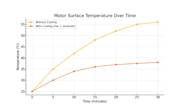
Original test results generated during in-house temperature benchmarking using a 57BYGH76-3A motor and DM542 driver (conducted in July 2025).
Avoiding these common mistakes isn’t about being perfect; it’s about being prepared. Understanding that not all NEMA 23s are the same, planning around your actual load, and respecting the heat your motor generates will set you up for long-term, reliable success. The better your foundation, the easier everything else becomes.
We’ve now explored every major aspect of the NEMA 23 stepper motor—from structure and function to selection and installation. To wrap up, let’s summarize the key takeaways to help you make confident, informed decisions for your next project.
Conclusion: From Theory to Reliable Performance
The NEMA 23 stepper motor isn’t just a common size—it’s a workhorse trusted across CNC machines, 3D printers, and automation systems. In this guide, we’ve demystified its core structure, selection process, and installation best practices, while also calling out critical mistakes to avoid.
Now it’s your turn to take action:
- Match your load: Calculate required torque based on moving mass, friction, and acceleration. Make sure your chosen motor’s
holding torque≥ required torque × 1.3 safety margin. - Check driver compatibility: For example, with a DM542 driver and a stepper motor rated at 1.8A, set DIP switches as follows:
SW1 = OFF, SW2 = ON, SW3 = OFF → Output current = 1.84A
(See Leadshine DM542 datasheet for full table) - Identify coil pairs using a multimeter: Set your multimeter to resistance mode. Measure between any two motor wires. A valid coil pair will show a resistance of approximately 1–2 ohms. Pairs with no continuity belong to separate windings.
- Verify motor direction: After powering on, issue a short move command. If the direction is reversed, either swap one coil’s polarity (e.g., A+ ↔ A−), or invert the DIR signal in your controller settings.
- Begin with safe motion tests: Set initial movement speed to
100 RPMand use low acceleration values. Listen for missed steps, stalls, or rough motion before ramping up performance. - Adjust microstepping for smoothness: On the DM542, set
SW5–SW8 = ON-OFF-ON-ONto enable1/8 microstepping, providing a good balance of precision and torque. - Monitor motor temperature: Use an infrared thermometer to check surface temperature at the motor center during operation. Try to stay below 60°C. If it exceeds this, reduce current or add active cooling like a fan or heatsink.
Whether you’re upgrading a benchtop CNC or designing a new pick-and-place system, following these principles will help you achieve smoother motion, longer lifespan, and fewer surprises down the line.
Looking for a wide range of NEMA 23 stepper motors or matching drivers?
Explore StepmoTech’s complete stepper motor catalog for options tailored to CNC, 3D printing, and automation applications.
Need a torque-speed curve, wiring diagram, or datasheet for your driver? Consider bookmarking this guide and sharing it with your team or community.
Frequently Asked Questions (FAQ)
What does “NEMA 23” mean in stepper motors?
Frame Standardization:
- “NEMA” stands for the National Electrical Manufacturers Association.
- “23” refers to the motor’s faceplate size: 2.3 x 2.3 inches (58.4 x 58.4 mm).
- Does not define torque, step angle, or electrical specs.
Can all NEMA 23 motors be used interchangeably?
Physical Fit ≠ Electrical Compatibility:
- ✔ Same mounting hole pattern across all NEMA 23s.
- ✘ Torque, current, voltage, and shaft design can differ significantly.
- Always check the motor’s datasheet before substituting.
Do I need a specific driver for a NEMA 23 stepper motor?
Driver Matching Is Essential:
- Choose a driver that matches your motor’s current & voltage specs.
- Popular choices:
DM542,TB6600,Gecko G540. - Wrong driver = overheating, stalling, or step loss.
What is the typical holding torque of a NEMA 23 motor?
Depends on Model Length & Coil Specs:
- Typical range: 0.9 Nm to 3.0 Nm.
- Higher torque = longer motor body + higher current draw.
- Check spec sheets from Pololu, Moons, Leadshine for exact values.
Can I run a NEMA 23 motor without a feedback sensor?
Yes—Most Run in Open Loop:
- Stepper motors don’t need encoders for basic operation.
- As long as torque margin is adequate, position remains accurate.
- Optional: closed-loop steppers add feedback to detect missed steps.
Do I need a specific driver for a NEMA 23 stepper motor?
Driver Matching Is Essential:
- Choose a driver that matches your motor’s current & voltage specs.
- Popular choices:
DM542,TB6600,Gecko G540. - Incorrect driver settings can cause overheating, stalling, or missteps.

Original diagram created to illustrate bipolar motor phase assignment and control signal routing for DM-series drivers (July 2025).
References and Further Reading
Oriental Motor NEMA 23 Stepper Motor Datasheet
Pololu NEMA 23 Stepper Motor Specifications (PDF)
Leadshine DM542 Stepper Driver Datasheet
RepRap Wiki: Stepper Motor Basics and Applications
CNCZone Forum – Stepper Motors and Drives Discussions
Duet3D Forum – Motor Driver Troubleshooting and Advice
First Published:
Last Updated: